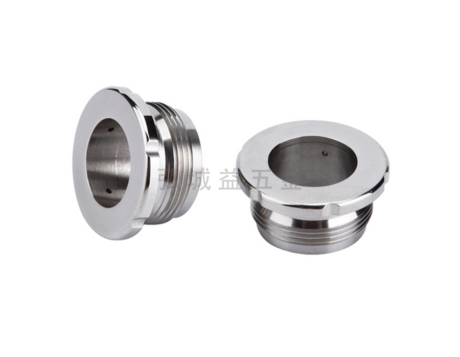
As long as CAD is simple, a Machine element usually needs to draw three drawings on a piece of paper: the front view (view from the front of the part), the front view (view from the top of the part), and the left view (see the picture on the left side of the part). Generally, simple parts can be clearly expressed by drawing these three diagrams, such as gear shafts. For a complex structure diagram, it is necessary to draw a cross-sectional view, which is enlarged locally. It is a section of a part, and its internal structure and dimensions are clearly expressed, such as screw holes, gearbox, gears, etc. It's not enough to know so much. If you want to know how to draw in detail, you should also look at the drawings of Machine element. In fact, most of the assembly drawings actually used have a lot of details to pay attention to. Practice more, and then read a book.

In addition, the outsourcing of Machine element also has its own standardized production. The United States has quantified Machine element, such as the length and diameter of screws. A series of parts have developed a unified standard, so that once a failure occurs, the machine can be easily repaired. This measurement is as wonderful as the unified writing, language and measurement of Qin Shi Huang of China!


