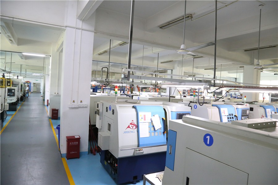
1. Check the appearance before powering on
CNC mechanical component processing machine tool electrical inspection. Open the electrical cabinet, check for loose sockets such as relays, contactors, fuses, servo motors, speed control unit sockets, and spindle motor speed control units. If loose, restore the normal state in a timely manner and tighten them. The mechanism of the connector must be locked tightly, and the junction box machine must check the adapter on the box to see if the connection is loose. If there is a locking structure, it must be locked properly. Open the electrical box door of the CNC machine tool, check various interface sockets, servo motor reaction line sockets, spindle pulse generator sockets, hand pulse generator sockets, CRT sockets, etc. If there is any looseness, plug and unplug from scratch, there must be a locking organization. According to the instructions, check the setting conditions of the short-circuit terminals on the printed circuit board, which must comply with the setting conditions of the machine tool factory. If it's really wrong, you should set it up from scratch. Under normal circumstances, it is not necessary to set it from scratch, but the user must make original records of the setting of the short-circuit terminal. Check the quality of all wiring terminals. Including strong and weak current, some wiring terminals connected by the machine tool manufacturer, and the wiring terminals of the power lines of each motor during installation. Each wiring terminal is fixed once with screws until the screws cannot be tightened, and the power socket must be tightened. To check all solenoid valves, it is necessary to manually operate them several times to avoid long-term poor operation without power supply. If any abnormalities are found, they should be recorded for maintenance or replacement after power supply. Check all limit switches for sensitive movement and loose fixation. If any poor movement or fixation is found, immediate action should be taken. Check the buttons and switches on the operation panel. Check the wiring of all buttons, switches, and indicator lights on the operation panel. If any errors are found, they should be dealt with immediately. The grounding wire inspection requires a protruding grounding wire, the measuring machine is grounded, and the grounding resistance should not exceed 1 Ω. Use a phase sequence meter to check the phase sequence of the input power supply and acknowledge that the phase sequence of the input power supply is definitely consistent with the phase sequence of the calibrated power supplies on the machine.

For equipment with secondary wiring, such as power transformers, it is necessary to recognize the commonality of phase sequence in secondary wiring. Ensure correct phase sequence. At this point, the power supply voltage should be measured and recorded
2. Connect the total voltage of the machine tool
On the power supply of the machine tool, check whether the electric box of the NC machine tool, the cooling fan of the spindle motor, and the cooling fan of the electric box of the machine tool rotate correctly and stably, whether the hydraulic oil symbol indicator light is normal, and whether the machine tool and fuse are damaged. If there is any abnormality, immediately cut off the power for maintenance. If there is no abnormality, proceed. Measure and record the voltage, especially the primary voltage of the power transformer used for CNC and servo units. Check for oil leakage, especially in hydraulic cylinders and solenoid valves for turret displacement, tightening, spindle displacement, and chuck tightening. If there is oil leakage, it should be immediately powered off for repair or replacement.
3. Powering on CNC electrical box
Press the CNC power button to turn on the CNC power, investigate the CRT display, and wait until the normal display stops. If there is an ALARM display, it is likely to identify the problem and clean it up. At this moment, it should be checked by powering on from the beginning. Turn on the CNC power supply and measure the voltage at all levels based on the orientation of the test terminals provided on the relevant materials. If there is an error, it should be adjusted to the given value and recorded properly. Place the status switch in the appropriate position, such as the Japanese FANUC system should be placed in the MDI status and selected to the parameter page. Check the parameters one by one, and these parameters should match the random parameter table. If different parameters are found, the meaning of each parameter should be clarified before deciding whether to correct it. For example, the value of backlash compensation may not be consistent with the parameter table, which can be corrected at any time after practical processing. Place the condition selection switch in the JOG direction, place the jog speed at a lower level, and perform jog operations in the positive and negative directions of each coordinate separately. Press the overtravel maintenance switch corresponding to the jog direction by hand to verify the reliability of its maintenance effect. Then, conduct a slow overtravel experiment to verify the correctness of the overtravel collision device. Place the status switch in the return to zero position and complete the return to zero operation. If the reference point return action is not completed, no other operations can be performed. Therefore, in this situation, this operation should be carried out first, and then the fourth operation should be carried out. Place the condition switch in the JOG or MDI position for manual gear change experiments. After verification, place the spindle speed control switch in a lower position and conduct spindle forward rotation experiments for each gear. Investigate the working condition of the spindle and the correctness of the speed display, and then gradually increase the speed to a higher speed to investigate the stability of the spindle operation. Conduct manual guide rail smoothing experiments to achieve outstanding smoothness. Gradually change the fast shift overshoot switch and feed rate switch, randomly move the tool holder, and investigate the correctness of the speed change.


